| 10-10-00-550-801-A | Parking and Storage Procedure It is not necessary to do all the scheduled maitenance task immediately during the storage/parking period. But you must do them all before the next flight.
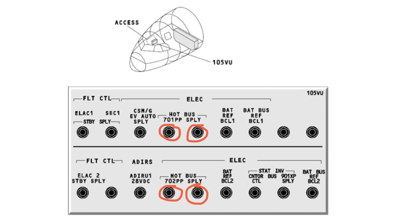
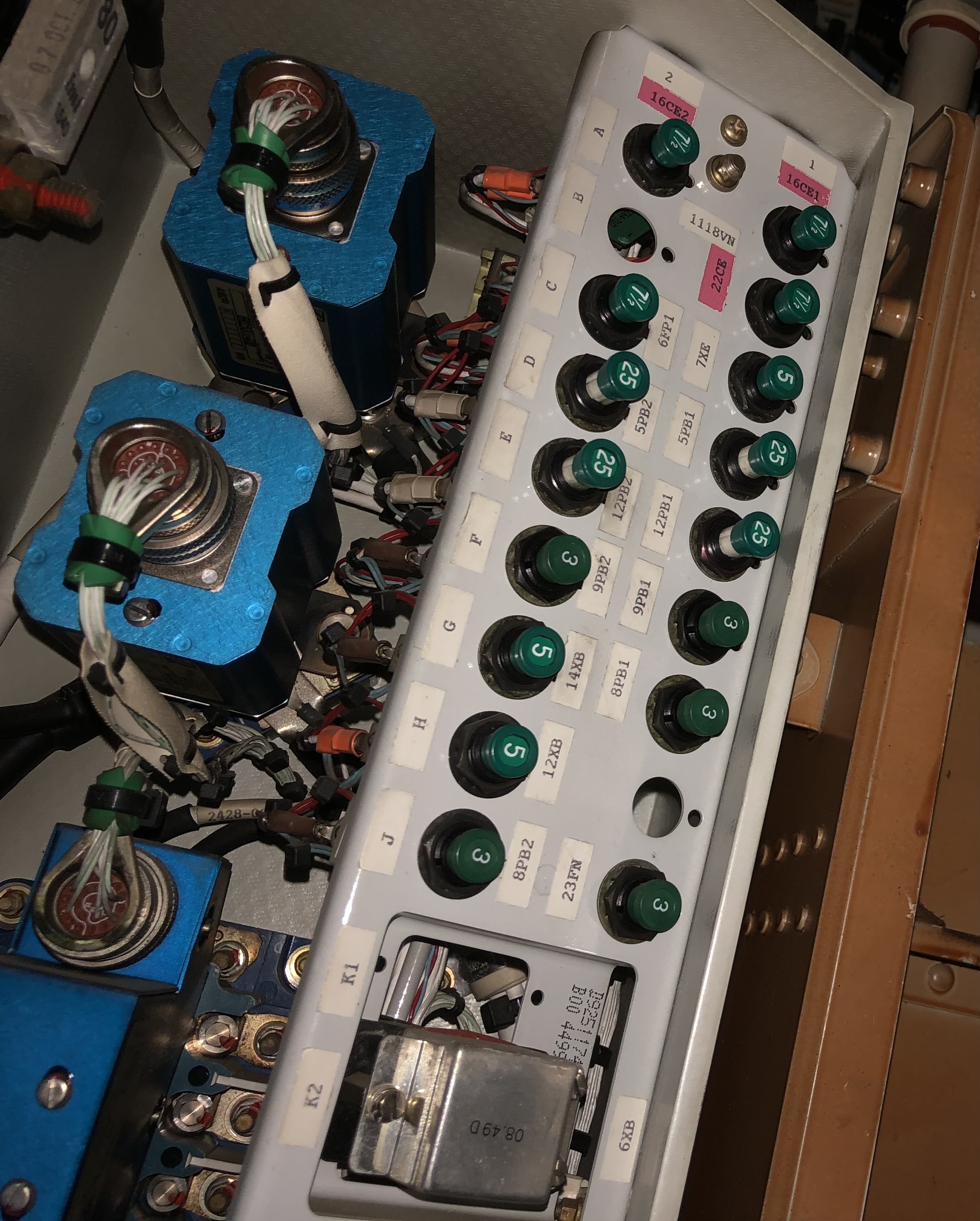
Parking and Storage Procedure also includes: AMM 12-31-38-02- Cold Weather Maintenance - Water/Waste * Subtask A: Pre-flight fill and leak check * Subtask B: Post-flight Water/Waste drain (includes air press, toilets, etc.) AMM 24-38-00-550-801-A On-wing Preservation / Return to Service of the Batteries * Do for parking period more than 2 days. * Ensure minimum voltage for preservation is more than 26V with batteries OFF, then open C/Bs. * Return to Service is vice versa. Close C/Bs and check 26V. |
| 10-11-00-02 | Installation / Removal of the Aircraft Protection Equipment (Engines, Probes)
|
| 10-11-00-555-804-A | Parking Periodic Ground Checks
It is not necessary to do all the scheduled maitenance task immediately during the storage/parking period. But you must do them all before the next flight. |
| 10-30-00-554-804-A | Return to Operational After a Parking Period |
| 12-11-28-650-006-A | Overwing (Gravity) Refuel |
| 12-11-28-650-007-A | Use of Magnetic Level Indicators (MLI) |
| 12-12-29-03 | Fill the Hydraulic Fluid Reservoir |
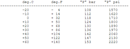
| 12-12-32-611-004-A | Functional Check of MLG Shock Absorber Fluid Level (This job included AMM 12-14-32-614-003-A Functional Check of MLG Shock Absorber Charge Pressure) xxxxxxxxxxxxxxxxxxxxxxxxxxxxxxx -> within limit -> Do the Hydraulic Replenishment of the MLG Two-Stage Shock Absorber iaw amm 12-12-32-611-008-A before 50 cycles (Aircraft on Jacks). -> Do the Hydraulic Replenishment of the MLG Two-Stage Shock Absorber iaw amm 12-12-32-611-008-A (Aircraft on Jacks). |
| 12-13-24-03 | IDG Oil Servicing |
| 12-13-49-03 | Check APU Oil Level and Replenish |
| 12-13-79-03 | Engine Oil – Servicing Full AMM: 12-13-79-610-002-A Check oil level and replenish Check Pop Out Indicator of EMCD (Electrical Master Chip Detector) |
| 12-14-29-614-001-A | Fill the Hydraulic Power Accumulators with Nitrogen |
| 12-14-32-03- | Nitrogen Filling of the Tires Full AMM: 12-14-32-614-001-A |
| 12-14-32-200-001-A | Inspection of the MLG Shock Absorbers before Flight -> Do the functional check of the MLG shock-absorber fluid-level iaw amm 12-12-32-611-004. -> Do the functional check of the MLG shock-absorber fluid-level before the aircraft completes five flight cycles, iaw amm 12-12-32-611-004. -> Do the functional check of the MLG shock-absorber charge-pressure at the next available maintenance check, iaw amm 12-14-32-614-003. |
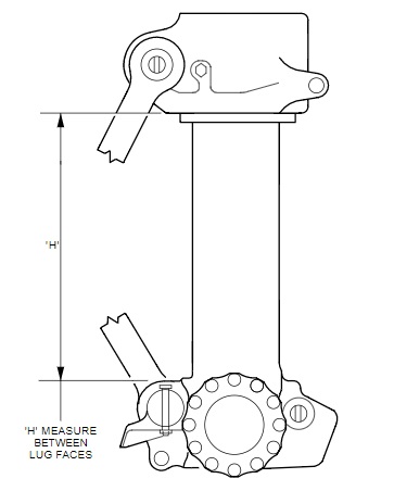
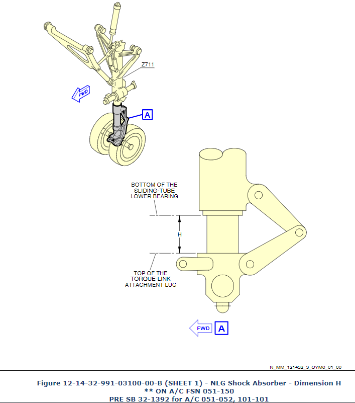
| 12-14-32-200-002-A | Check of the NLG Shock Absorbe Bottoming Out of limit, if the dimension H: Is less than 26 mm, when the ambient temperature is less than 0 deg.Cor is less than 48 mm when the ambient temperature is between 0 deg.C and 30 deg.C or is less than 72 mm, when the ambient temperature is more than 30 deg.C . xxxxxxxxxxxxxxxxxxxxxxxxxxxxxxxxxxxxxxxx Out of limit leads to: AMM 12-12-32-610-001-A01 Check NLG Shock Absorber Fluid Level and Charge Pressure ("Two-Point Check" - Aircraft on Ground to start) (NLG on the jack)or AMM 12-12-32-611-001-A NLG Shock Absorber Oil Replenishment and Nitrogen Filling (Aircraft on Wheels)xxxxxxxxxxxxxxxxxxxxxxxxxxxxxxxxxxxxxxxxxxx Job "Check of Bottoming" not leads to: AMM 12-14-32-614-004-A Check of the NLG Shock Absorber Charge-Pressure |
| 12-14-32-614-002-A | Nitrogen Filling of the Yellow Hydraulic System, Brake Pressure Accumulator +- 50psi
|
| 12-14-32-614-003-A | Functional Check of MLG Shock Absorber Charge Pressure -> within limit -> Check and adjust nitrogen pressure on both filling ports (first make sure than bottom one has more then 261 psi compare to upper one). -> Functional Check of the MLG Shock Absorber Charge-Pressure and Nitrogen Filling (Aircraft on Jacks). |
| 12-14-32-614-004-A | Check of the NLG Shock Absorber Charge-Pressure |
| 12-15-38-03- | Fill the Potable Water Tank System Full AMM: 12-15-38-613-001-A |
| 12-24-38-02- | Draining of the Potable Water System Full AMM: 12-24-38-680-001-A * Operate the water faucet(s), the coffee makers and the water heater in the galley(s) (if installed) to drain them. (no press air necessary) |
| 12-31-38-02- | Cold Weather Maintenance - Water/Waste (Subtask A: Pre-flight fill and leak check; Subtask B: Post-flight Water/Waste drain) Full AMM: 12-31-38-660-001-A included:* The air (without water) comes out of the water faucet. * Flush the toilet until the air (without water) comes out of the toilet |
| 12-31-71-02- | Cold weather maint. - power plant. (Use hot air blower to remove all traces of ice and residual water before engine start up) Ful AMM: 12-31-71-660-001-A |
| 32-43-00-710-001-A | Nitrogen Filling of the Yellow Hydraulic System, Brake Pressure Accumulator Limit before filling is +/- 50PSI
|
| TASK 12-12-32-611-008-A | Hydraulic Replenishment of the MLG Two-Stage Shock Absorber (Aircraft on Jacks)
|
| 20-28-00 | smazat For Bonding lead at cargo door actuator IPC 52-36-04-08D
|
| 20-28-00-200-001-A | Detailed Inspection of Bonding Leads on Access Panels, Doors and Movable Surfaces Replace the bonding lead at the next maintenance visit, before 6 months, 1000 Flight Hours (FH) or 1000 flight cycles, whichever occurs first if the bonding lead is broken or if more than 25% of the strands are damaged (less than 75% not damaged) NOTE: Cargo doors need resistance check for deferral 24-92-00-210-024-A Detailed Inspection of Bonding Leads Located on the Following Movable Surfaces: Elevator, Rudder, Flaps, Flap Track Fairings, Slats, Spoilers, Ailerons,....... IPC For Bonding lead at cargo door actuator IPC 52-36-04-08D Crew door IPC 52-13-04-04E |
| 20-28-00-912-802-A | Electrical Bonding - General Maintenance Procedure (replacement) Polysulfide Sealant
+
When the sealant is cured, apply Varnish-- Electrical Bonding Structure (Material Ref. 04TMB2) or Coating-- Flexible Structure (Material Ref. 04QAB2) with the BRUSH - BRISTLED, SMALL to overlap the sealant layer.
|
| 21-26-00-710-001A | OPERATIONAL TEST OF THE AVIONICS EQUIPMENT VENTILATION SYS. VIA MCDU |
| 21-61-00-710-001-A | Operational Test of the Pack Temperature-Control System Bite test via MCDU (4min) |
| 22-70-00-610-008-C01 | Uploading of the Flight Management (FM) Data to FMGC - DLS ON
- Open C/Bs
- DLS NEXT key
- DLS SEL CTL key
- Insert disk
- Close C/B
|
| 22-83-34-04 | Installation of the Flight Management and Guidance Computer (FMGC) - AFS Test - Softwares checking |
| 22-910-710-001-A | Ground scanning of the Automatic (AFS) * Inertial Reference (IR) alignment procedure needed
* Pressurize the aircraft hydraulic systems needed (pumps)
|
| 22-96-00 | Operational Test of the AFS (BITE Test)) Full AMM: 22-96-00-710-001-A * AFS MAIN MENU page: Push the line key adjacent to the AFS TEST
|
| 22-97-00-710-001-A | Operational test of the land CAT 3 capability |
| 23-73-00 | CIDS; Interface + Power-Up Test ( 6 min) Full AMM: 23-73-00-740-005-B Interface and Power-Up Test of the Cabin Intercommunication Data System (CIDS) through the CFDS MCDU:
|
| 23-73-00-04 | Installation of the Passenger Interface and Supply Adapter (PISA) |
| 23-73-45-04 | Pasenger Service Unit (PSU) replacement |
| 24-92-00-210-024-A | Detailed Inspection of Bonding Leads on Access Panels, Doors and Movable Surfaces During the inspection, if you cannot replace the bonding leads that are broken or damaged, the installations that follow are satisfactory: * a.) xxx * b.) xxx * Replace all the remaining broken or damaged bonding leads in less than 24 months or 7500 flight hours or 5000 flight cycles (the one that occurs first). * * xxxxxxxxxxxxxxxxxxxxxxxxxxxxxxxxxxxxxxxxxxxxxxxxxxxxxxxxxxxxxxxxxxxxxxxxxxxxxxxx * 20-28-00-200-001-A Detailed Inspection of Bonding Leads on Access Panels, Doors and Movable Surfaces |
| 25-13-11-04 | Replacement of the Windshield Sunvisor |
| 25-21-00-210-001-A | Detailed Inspection of Seat (Attachment, Structure, Belts, Buckless, Baggage bar) |
| 25-22-41-04 | Wall-Mounted Cabin Attendant Seat - Change |
| 25-22-41-04 | Spring of the JPS - Change NOTE: CHOOSE THE LEFT OR THE RIGHT VARIANT OF SPRING PART NUMBER IS DEPENDING TO THE SEAT ORIENTATION.
Full amm for jumpseat change: 25-22-41-04 Installation of the Wall-Mounted Cabin Attendant Seat (CAS) |
| 25-35-00-710-013-A | Operational Test of the Coffee Maker |
| 25-35-00-710-015-A | Operational Test of the Oven |
| 25-35-15-04 | Change of the Coffee Maker |
| 25-35-19-04 | Change of the Oven |
| 25-35-27-04 | Change of the Water Boiler/Heater |
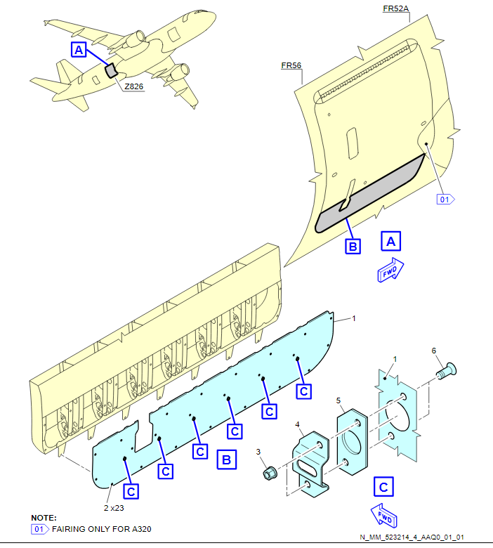
| 25-50-00-200-002-A | Visual Check of Cargo Compartment (more links in info) Visual Check of Cargo Compartment Decompression, Lining, Floor Panels and Ventilation Extraction Duct AMM is referring as well to: AMM 25-50-00-200-024-A Cargo Compartment Linings With Honeycomb Core - General Repair/Protection Information *Damaged panel can be deferred for the repair in 100 Flight Hours (FH) and Inspection For Missing Fastener(s) and Temporary Repair of the Aft Cargo-Compartment Lining-Panel(s) AMM 25-54-12-300-001-A (Fwd Cargo) AMM 25-55-11-300-001 (Aft Cargo) AMM 25-55-12-300-001 (Bulk Cargo) * FOR DEFERRED FASTENERS USE Aluminium Foil and do a visual inspection of each lining panel on which you did a temporary repair as follows, Inspection Interval and Action: 0-100 flight hours (10 days) after you find the defect. Do a visual inspection one time each week. 101-500 flight hours (50 days) after you find the defect. Do a visual inspection one time each day. Maximum 500 flight hours (50 days) after you find the defect. Remove the adhesive tape and do step (1). |
| 25-55-00 | SMAZAT to be delete
|
| 25-66-52-04 | Change of the Life vest |
| 27-51-00-05 | BITE Test of the SFCC (This is AMM for Flap System) 2 x SFCC (Slat and Flap Control Computer) Full amm: TASK 27-51-00-740-002-A BITE Test of the Slat and Flap Control Computers (Flap System) |
| 27-81-00-05 | BITE Test of the SFCC (This is AMM for Slat system) 2 x SFCC (Slat and Flap Control Computer) TASK 27-81-00-740-002-A BITE Test of the Slat and Flap Control Computers (Slat System) |
| 27-96-00-740-001-A | Operational Check of EFCS by BITE (Ground Scanning) The flight control computers consists of two Elevator Aileron Computers (ELACs), three Spoiler Elevator Computers (SECs), and two Flight Augmentation Computers (FACs). * Inertial Reference (IR) alignment procedure needed |
| 28-25-00-869-001-A | Fuel Transfer In cockpit X FEED ON, PUMPs to ON, On fueling panel MODE SELECT switch to DEFUEL XFR, related REFUEL VALVES to OPEN
|
| 28-25-48 | LAMP FROM REFUEL GREEN LIGHT AT L/H WING - CHANGE |
| 28-42-00-740-001-A | Status Report (BITE) TEST: MCDU--FUEL-FQIS STATUS => NO FAULT DETECTED
***ADIRS start procedure required
***
***note: there need to be min 1500kg in wing for cadensicon 19QT1 (19QT2)
***or 2000kg in center for 20QT
|
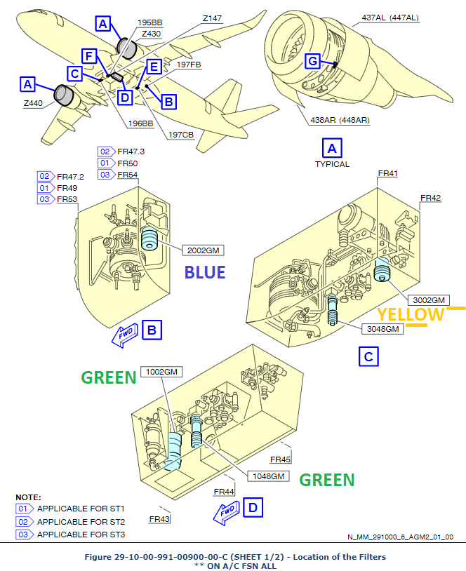
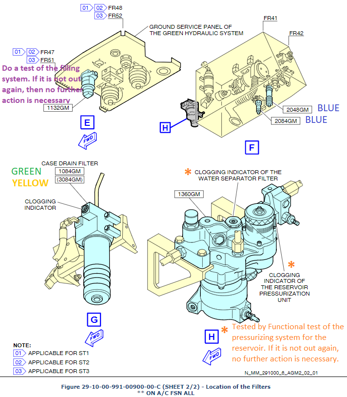
| 29-10-00-210-002A | Check Clogging Indicators |
| 29-22-00-720-003-A | Operational Check of RAT Manual Deployment and Functional Check of RAT Manual Deployment and Functional Check of RAT using Ground Test Unit, followed by Check of Filter Indicator |
| 32-00-00-02- | Installation / Removal of the Safety Devices on the Landing Gears
|
| 32-41-00-210-002-A | Inspection/Check of the Wheels and Tires |
| 32-41-11-04 | MLG Wheel Change A319/320 tighten 220-70-110 lbt/ft A321 tighten 320-0-160 lbt/ft |
| 32-41-12-04 | NLG Wheel - Change tighten 160-0-80 lbt/ft |
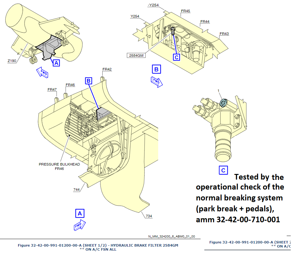
| 32-42-00-710-802-A | Operational Check of the Hydraulic Brake Filter Brake filter (2584GM) . Indicator button is out => Replace the filter element and push indicator button => Operational test of the normal braking system => (1) Indicator is out again => Replace the clogging indicator. (2) Indicator is not out => Do a check the clogging indicator again after the next two flights => If indicator is not out, close the defect, if it is out see AMM
|
| 32-42-27-04 | Brake - Change Tighten 160 lbf.ft |
| 32-44-11-200-001-A | Functional Check of Parking/Emergency Brake Accumulator by Reading the Charge Presssure on the Accumulator Gauge * PARK BRK control-switch off
* Depress hyd. from brake accu.
* Wait 10min and read the pressure-gage. Limit is +/- 50PSI (if necessary: AMM 12-14-32-614-002-A
Nitrogen Filling of the Yellow Hydraulic System, Brake Pressure Accumulator)
* Perform AMM 32-43-00-710-001-A Operational Check of Alternate Braking System
|
| 32-45-00-720-002-A | Functional check of the Brake Accumulator System with the Parking Brake Applied To do a leakage test of the Brake Accumulator System
* min 2321 PSI after 3h.
|
| 33-21-11-04 | Replacement of the Fluorescent Tube in the Ceiling Panel |
| 33-41-11-04 | Wingtip Navigation Light - Change |
| 33-41-15-04 | Tail Navigation Light - Change Lamp P/N: 8GH005597-12 |
| 33-42-11-04 | Landing Light – Change |
| 33-43-11-04 | Runway Turnoff Light – Change LAMP P/N: 4626
|
| 33-46-11-04 | Take Off Light – Change |
| 33-46-12-04 | Taxi Light – Change |
| 33-47-11-400-802 | Logo Light Lens - Change Lamp PN: 4626
|
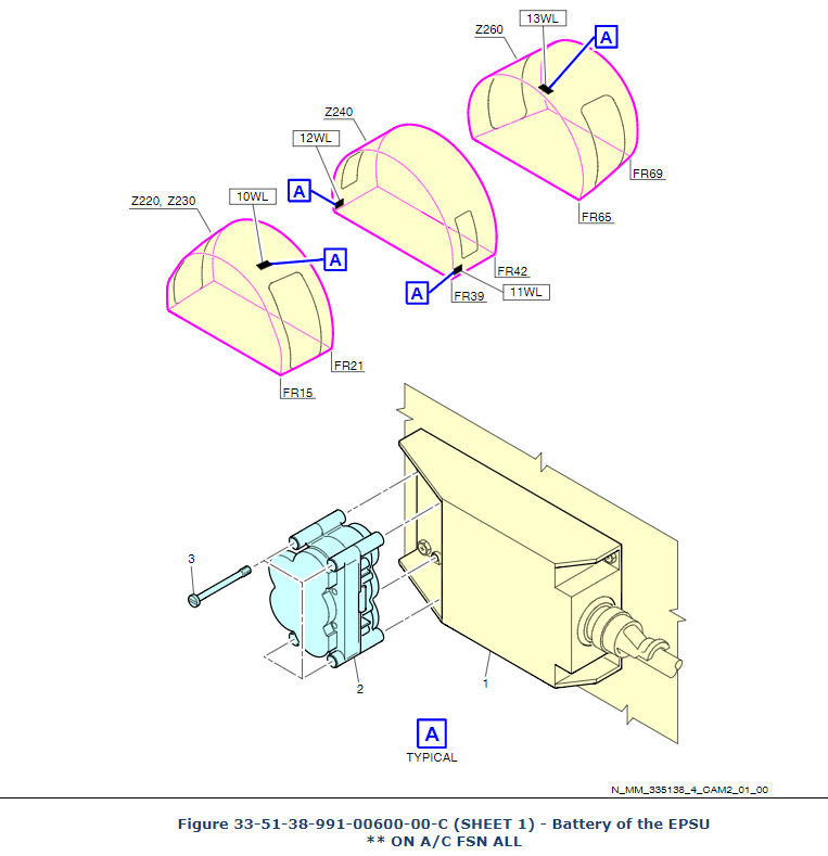
| 33-51-38-04 | Battery of the Emmergency Power Supply Unit (EPSU) - Change |
| 35-11-41-04 | Crew Oxygen-Storage Cylinder - Change (fixed bottle in avionic compartment) |
| 35-21-42-04 | Emergency Oxygen Generators RPLC |
| 35-32-42-04 | Change of the Portable oxygen cylinder |
| 35-32-42-06 | Inspection of the Portable oxygen cylinder |
| 36-11-00-040-003A | HP VALVE SECURED IN CLOSE POSITION |
| 36-11-00-740-001 | A BITE TEST OF THE BMC (BLEED MONITOR COMPUTER) Pneumatic system operation is controlled and monitored by two bleed monitoring computers (BMCs). |
| 38-12-16 | Installation of the (Lavatory) Water Heater |
| 38-31-00-710-009-A | Operational Test of the Toilet Unit |
| 38-32-00-100-002-A | Clean Filter Element of Washbasin Drain Valves |
| 38-42-00-710-001 | Operational test of the Compressor |
| 52-10-00-210-004-A | Check Pressure of Emergency Cylinder/Accumulator of the Passenger/Crew Doors |
| 52-10-00-220-006-A | Detailed Inspection of Door Seals |
| 52-10-00-614-001-A | Discharging/Charging of the Door Damper and Emergency Operation Cylinder of the Passenger/Crew Doors |
| 52-11-18-300-002-A | Repair of the Rubbing Strips of the Cover Plate of the Forward Passenger/Crew Door iaw AMM can be deferred with inspection every 50FC. After 550 FC, install the new rubbing strip.
PN: can be found in SRM 52-13-00-04-A Needed: Adhesive at Neopren base (05JBC9), Polysulfide Sealent (06AAB1), Rubbing strip
|
| 52-32-14-400-801-A | Installation of the Aft Cargo-Compartment-Door Access-Panels + Sight glass
DD item
|
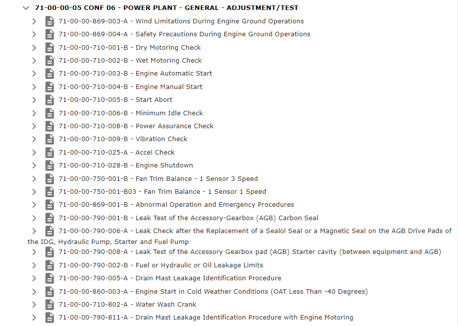
| 71-00-00-05 | Power plant - General - Adjustment/Test |
| 71-00-00-710-001-B | Dry Motoring Check xxxxxxxxxxxxxxxxxxxxxxxxxxxxxxxxxxxxxxxxxx Starter limit: |
| 71-13-00-410-040-B | Eng fan cowls closed and secured |
| 72-21-00-210-009-A | Inspection of Fan Rotor Blades Installed on the Fan Disk Defect entry:
Nick(dent) on leading edge 58mm from the tip of the blade No.9. Action example: Blending of the Fan Rotor Blade performed. Fan blade damage record opened for reworked dent located on leading edge, 58mm from the tip of the blade No.9. Reworked dimension L=7, D=0,4 within limits iaw amm 72-21-00-320-003-A rev X. Note: max D on the leading edge is 8,6mm Note: reworking on leading edge: Min radius 15x deept, min lenght 10x deept. Note: amm 72-21-00-210-009-A (Inspection of Fan Rotor Blades) . Note: amm 72-21-00-320-003-A (Blending of the Fan Rotor Blades). |
| 73-29-00-710-040-B | Operational Test of the FADEC on the Ground (with Engine Motoring) Job Set-up:
|
| 73-29-00-710-040-B02 | Operational Test of the FADEC on the Ground (with Engine Non motoring) Job Set-up:
|
| 78-32-11-220-040-B | General Visual Inspection of the Inner Barrel Heatshield, Fire Protective Coating and Fire Seals
***if more ***monitor at 750 flight cycles / 4 calendar months (whichever the earliest), or repair Ref. NSRM 543000 (51563), Rep.No.12. |
| 79-00-00-281-002-A | Check of the Electrical Master Chip Detector (EMCD) for Particles note: This inspection is required when the pop-out on the visual indicator is extended during operation.
*
note: The inspection of the Electrical Master Chip Detector can be deferred to the next convenient maintenance opportunity (new o-ring need).
*
See TSM link: 79-00-00-810-833-A
*
Report:
The Electrical Master Chip Detector indication is popped out - Engine 1(2)
*
Action:
The Electrical Master Chip Detector (EMCD) checked for Particles iaw amm 79-00-00-281-002-A. No findings, the visual indicator reseted.
|

